
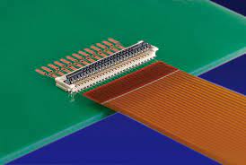
Flex Circuit Board
A flex circuit board is an electronic printed circuit board that is designed to bend and/or flex. This type of PCB is often used for a number of different applications including:
Flex circuits are able to bend and flex due to the use of extremely thin materials for the substrate layer, conductive material, and insulator layers. The substrate is typically made from FR-4 or polyimide while the conductive metal layer can be made of copper or aluminum foil. The insulator layers are typically made of polyester, polyimide, or a combination of these materials.
The layer stack is then etched to form the desired flex circuit board and to create pad traces, through holes (vias), and other necessary electrical connections. A coverlay is then applied to protect the layers from moisture and other environmental factors.
In order to create the required circuit pattern on the conductive layer of a flex PCB, a photolithography and etching process is utilized. The photolithography applies a resist to the copper foil while the etching removes the areas of copper not needed for the circuit design. This allows the designer to create the desired flex circuit path layout.
What Is a Flex Circuit Board?
Once the flex circuit has been patterned, it then goes through a number of quality and inspection processes. These include a visual inspection to verify the integrity of the flex circuit as well as an electrical testing to ensure proper signal flow and connection between all layers. Once the flex circuit passes these tests it then undergoes the assembly process. During the assembly process, electronic components are mounted on the flex circuit using surface mount technology. These components are then soldered to the traces and pads on the flex circuit using reflow soldering.
When designing a flex circuit it is important to take into account the amount of bending that it will be required to withstand. It is also important to use the correct materials for fabrication of the flex. In particular, the choice of copper foil is critical. While cheaper electrodeposited copper foil may be suitable for most applications, higher-grade rolled annealed copper is an excellent choice for flex circuits that will be flexed and folded frequently. This is because the rolling annealing process increases the copper’s elastic properties in the Z deflection direction.
Finally, a flex circuit design must also include appropriate strain relief for the pads and traces on both the flex and the rigid sections of the board. This is done by utilizing either teardrop (pad fillet) or annular rings. Both are effective in reducing stress concentration points.
Flex PCBs are increasingly being used in a wide variety of electronics including calculators, cell phones, printers, LCD televisions, cameras, and medical equipment such as heart monitors and pacemakers. Additionally, a wide variety of industrial and consumer products use flex circuits including robotic arms, processing machines, bar code equipment, and aerospace/military applications. In all of these applications, a flex circuit provides the benefits of weight reduction and space savings that are unobtainable with traditional rigid or hand-wired designs.